How to install CAT5E Ethernet Cable connector?
- lan cable
- 17 Jun, 2021
How to make a network patch cable? How to check whether the network cable is done well? For details, please refer to the network cable and network plug connection diagram. Network cables such as CAT5, CAT5E and CAT6 are widely used in enterprise networks, data center networks or family networks. More and more network cable types are gradually being invented. They can support different transmission distances and applications. The CAT5e network cable can support 1000base-T applications, and the transmission distance is up to 100m, which can fully meet the needs of various applications in families, offices and data centers. CAT5E has better performance than CAT5, and lower price than CAT6. These advantages make it one of the most widely used types of network cables.
The Structure of CAT5E
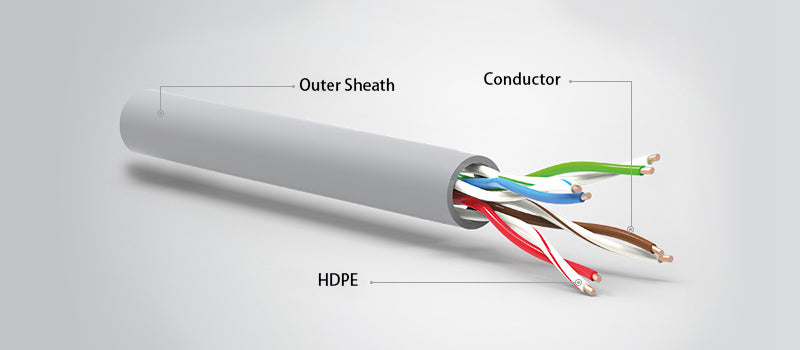
As shown in the below picture, CAT5E LAN cable consists of copper conductor, HDPE and outer sheath. Each CAT5E network cable has four copper wires inside, and its end is connected to the RJ45 connector ( Crystal head) connected. There are two types of CAT5e cables: straight-through and cross match. The difference between straight-through and cross match will be explained in detail below.
Wiring Method of CAT5E cable
Each pair of copper wires in the CAT5E network cable has a specific color insulation layer for easy identification. Therefore, during the crimping, the standard color code of the CAT5E network cable must be followed for the wiring operation.
There are two standards recognized by ANSI, TIA and EIA for the connection of the straight-through network cable: T568A and T568B. Both standards can be used. However, T568B is considered to be better than the T568A wiring standard. The following figure is the wiring diagram of the two standards.
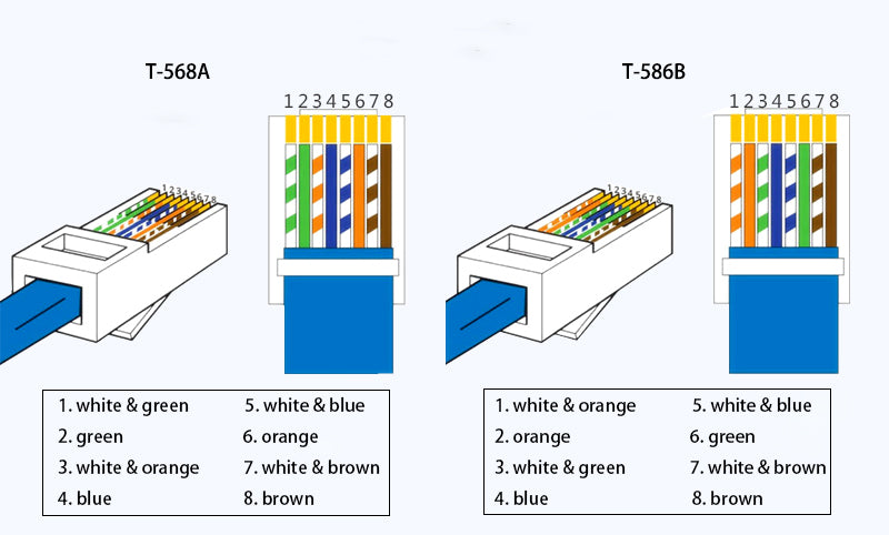
When you are doing straight-through wiring, the cable outlets at both ends of the CAT5e cable should be the same. However, for the cross match, the RJ45 lead wires at both ends of the CAT5e cable are different. The figure below is a schematic diagram of the cross termination of 8 wires.
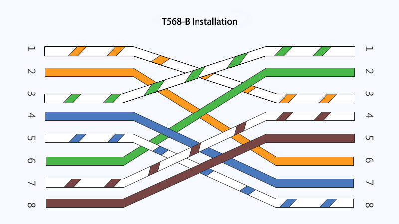
In fact, if you want to connect T568A equipment and T568B equipment, you can use this cross match method. The following figure shows the lead wires at both ends of the CAT5E network cable.
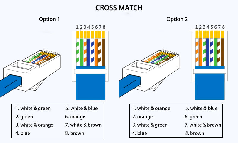
How to install CAT5E Ethernet Cable connector?
Tools for Connector Crimping
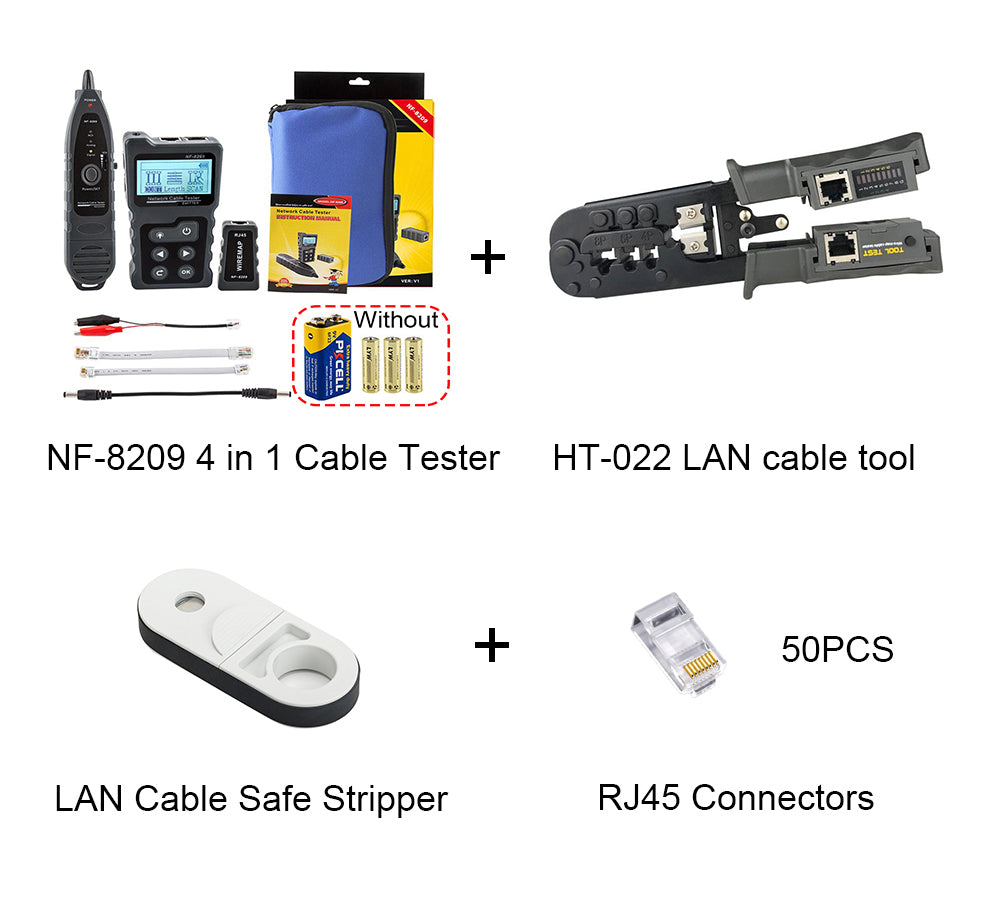
There are mainly three tools which are needed in the coming installation.
Fiber Cable Stripper
The first tool is a cable-jacket stripper. It will only cut through the outer jacket of the cable, not through the conductors inside. Many different kinds of cable strippers exist, but the most common are the small, plastic ones that easily fit into a shirt pocket. They are cheap to produce and purchase.
Cable Connector Crimper
A cable connector crimper is needed when installing connectors on UTP or STP cable. Many different styles of cable crimpers can crimp connectors on UTP or STP cables. Here is an example of a crimper that can crimp both RJ-11 and RJ-45 connectors.
Network Cable Tester
The last tool you are going to use is a cable tester. This device tests for a continuous signal from the source connector to the destination and also tests the quality of that connection.
Installing Steps
Now we will go over the steps for installing the connectors. Pay particular attention to the order of these steps and be sure to follow them exactly. Equipment from some manufacturers may require you to perform warning slightly different steps. Check the manufacturer's instructions before installing any connector.
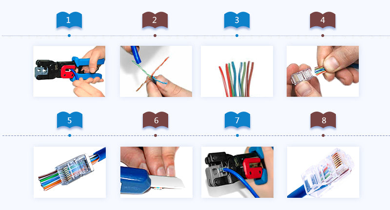
Step 1: Measure the cable you want to put ends on and trim it to the proper length using the cable cutter.
Step 2: Use the cable stripper to strip about 1.5" of the jacket from the end of the cable. Then, rotate the stripper around the cable twice. This will cut through the jacket.
Step 3: Remove the stripper from the cable and pull the trimmed jacket from the cable, exposing the inner conductors. If a jacket slitting cord (usually a white thread) is present, separate it from the conductors and trim it back to the edge of the jacket.
Step 4: Untwist all the inner conductor pairs and spread them apart so that you can see each individual conductor.
Step 5: Line up the individual condutors so that the color code matches the color-coding standard you are using.
Step 6: This step includes two points. First, trim the conductors so that the ends are even with each other, making sure that the jacket of the cable will be inside the connector. Second, the total length of exposed connectors after trimming should be no longer than 0.5" to 0.625".
Step 7: Insert the conductors in the connector, ensuring that all conductors line up porperly with the pins as they were in the previous step. If they don't line up, pull them out and line up. Do this carefully, as it's the last step before crimping on the connector.
Step 8: Carefully insert the connector and cable into the crimping tool, which has two dies that will press into the connector, and push the pins in the connector into the conductors inside the connector. Now the installation is done.
After the whole installation, you should check to ensure all conductors are making contact and that all pins have been crimped into their respective conductors. If the connector didn't crimp properly, cut off the connector and redo it.


